Ever wonder where life safety drawings came from, and why they still lead every drawing set?
Rooted in the aftermath of historic fires and decades of evolving code, these documents remain the architect’s clearest tool for demonstrating code compliance.

Introduction
Life safety documentation is one of the most critical, yet least glamorous, components of architectural design. It’s rarely celebrated, often misunderstood, and almost never admired for its aesthetics. But within every new building or major renovation, these documents play a foundational role in protecting public health, safety, and welfare. They’re not an afterthought, they’re the starting point. Before any architectural plans are reviewed for layout, materials, or detailing, the life safety sheets are consulted first. They sit at the front of the drawing set and form a significant portion of the general series. Their purpose is clear: to demonstrate how the design addresses egress, fire protection, compartmentation, and emergency response, both in code logic and graphic clarity.
These drawings are used by code reviewers, building officials, and fire departments to verify compliance with nationally adopted model codes like the International Building Code (IBC), as well as nationally recognized standards such as NFPA 101 (Life Safety Code), which may be adopted by reference depending on the jurisdiction, along with local amendments enforced in every U.S. state and territory.
At their core, life safety drawings are a form of technical storytelling, a blend of written code analysis and graphic plans that illustrate how occupants can safely evacuate a building under emergency conditions. These drawings illustrate egress paths, fire-rated assemblies, occupancy classifications, travel distances, areas of refuge, and might also show standpipes, FA alarm devices, or other relevant features. Although the specific submission format varies by jurisdiction, nearly all U.S. building departments require life safety documentation as part of their code review process.
Life safety documentation reflects the requirements of modern building codes, which place occupant welfare at the center of emergency planning. According to the National Fire Protection Association (NFPA), U.S. fire departments respond to an estimated 18,700 non-residential building fires each year, resulting in over 160 civilian deaths, approximately 1,300 injuries, and extensive property damage While detailed data on the specific building types involved in these incidents is often incomplete or generalized, the overall numbers underscore the ongoing threat to occupant safety across a broad range of public and private spaces. Life safety documentation helps address this risk by showing how buildings comply with code-required paths of egress.
The Evolution of Life Safety and the Rise of the Modern Code System
While modern building codes are a relatively recent development, the concerns that underpin them have shaped design thinking for centuries. In ancient Greece and Rome, the need to manage large crowds in theaters and arenas led to early innovations in circulation and egress. These principles, wide corridors, tiered access, multiple exits, weren’t about fire protection, but about moving people safely.
By the Middle Ages, fire risk had become a dominant concern in dense urban environments. Major events like the Great Fire of London in 1666 spurred early regulations on materials and building layout, including bans on timber construction and requirements for fire-resistive construction. These municipal rules set a precedent for local governance of life safety in the built environment.
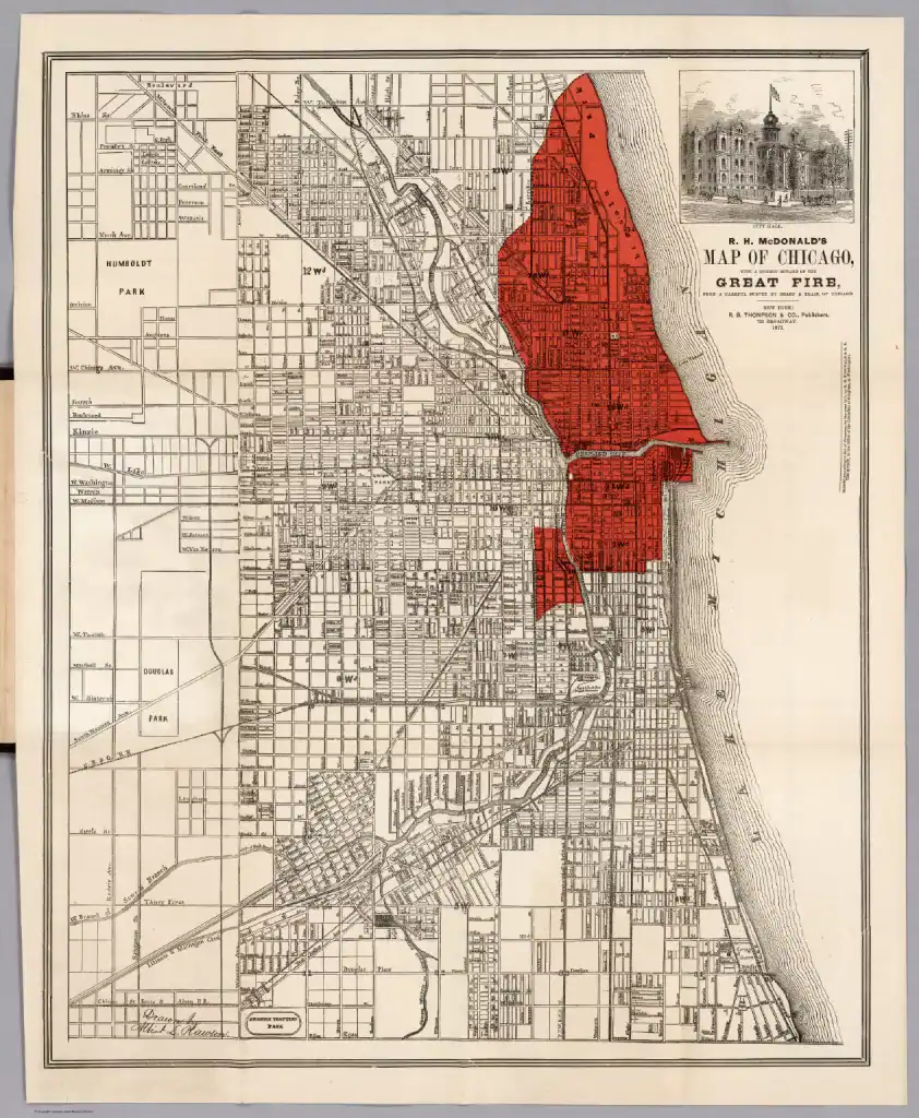
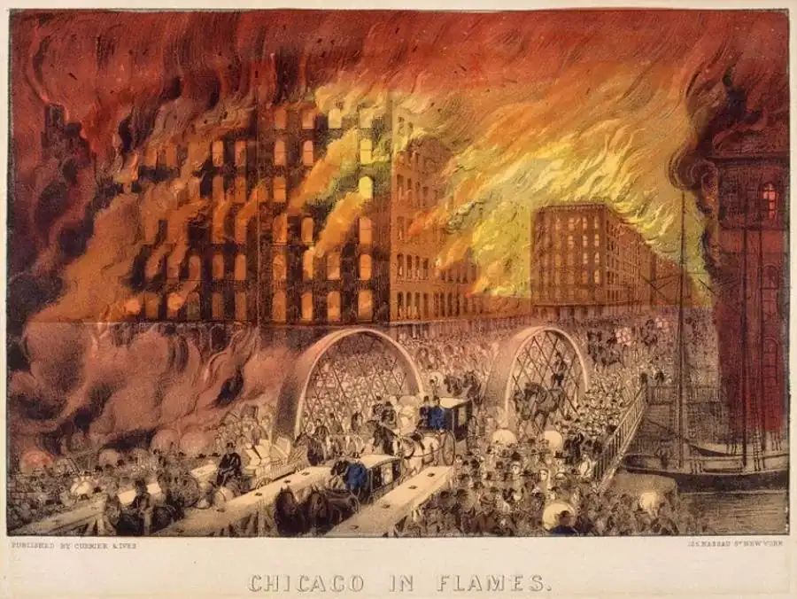
In the 18th and 19th centuries, deadly theater fires in cities like Paris, Vienna, and Brooklyn prompted more formal requirements: safety curtains, firewalls, designated exits, and eventually illuminated signage. In the U.S., the 1871 Great Chicago Fire led to one of the first municipal building codes in 1875, addressing fireproofing, height limits, and materials. Tragic fires at the Triangle Shirtwaist Factory (1911) and Cocoanut Grove nightclub (1942) further galvanized public demand for regulatory oversight.
By the mid-20th century, regional model codes became the dominant structure for code enforcement in the U.S. These included:
- The Building Officials and Code Administrators (BOCA) for the Northeast and Midwest
- The International Conference of Building Officials (ICBO) for the West
- The Southern Building Code Congress International (SBCCI) for the South
Each code addressed life safety, fire protection, and structural requirements, but the lack of consistency across jurisdictions created difficulties for national design and construction teams. In response, the three organizations merged in 1994 to form the International Code Council (ICC), which released the first edition of the International Building Code (IBC) in 2000.
Today, the IBC is the most widely adopted model building code in the United States. It has been adopted by all 50 states, though many jurisdictions, including major cities like New York, Chicago, and others, maintain their own codes or modify the IBC extensively through local amendments. The IBC brings together requirements for egress, fire protection systems, and related code provisions into a single coordinated structure. Though primarily prescriptive, defining what conditions must be met rather than how to achieve them, it allows for alternative methods under Section 104.11 when justified by engineering rationale. This flexibility is especially important for complex or unconventional projects, where compliance may require custom solutions backed by analysis and agency review.
As building codes evolved, so did the role of life safety documentation. These drawings became an essential part of the design process, translating regulatory requirements into clear diagrams and plan references that reviewers can evaluate directly.
In addition to the IBC, several supplemental codes and standards influence how life safety requirements are interpreted and implemented:
- NFPA 101 – Life Safety Code: A performance-based standard that addresses egress and fire protection in both new and existing buildings. It often applies to operations and maintenance beyond initial construction.
- ANSI A117.1: Defines technical accessibility criteria such as clearances and reach ranges. Incorporated into most codes through Chapter 11 of the IBC.
- ADA: A federal law that mandates accessibility in public and commercial buildings. Compliance with the ADA is required in addition to local building codes.
- ASTM Standards: Provides testing methods and material standards used throughout the IBC, for fire ratings, slip resistance, and more.
- OSHA Regulations: Workplace safety standards that may affect stairs, railings, and lighting during construction and occupancy.
- Structural Standards (ASCE 7, AISC, ACI): Referenced by the IBC for structural design criteria including loading, steel, and concrete construction.
Together, these standards and regulations create a layered system. In some building types or jurisdictions, more restrictive requirements from sources like NFPA 101 or the FGI Guidelines may take precedence. When this happens, the most stringent applicable requirement governs. Architects must review all overlapping codes carefully to ensure consistency across life safety drawings and code analyses.
The IBC sets baseline expectations to help buildings perform effectively under emergency conditions. It defines clear criteria while allowing justified flexibility, supporting practical solutions that maintain safety without limiting design.
Translating Code into Drawings: Understanding the Building First
Before any life safety drawing is developed, a thorough understanding of the building is required, not in terms of its program or design vision, but in terms of how it will be evaluated under the building code. While the IBC serves as the basis for most U.S. building codes, including those with local amendments, the process generally starts with key classifications that determine how the code applies to a particular project. These factors – use, size, height, materials, fire protection, and location, establish the criteria against which all life safety provisions are measured. Getting this baseline right is essential. It affects everything from egress width to fire-resistance ratings and sprinkler requirements.
The following steps outline how to evaluate a building from a code perspective and set the stage for life safety documentation:
1. Determine Occupancy Classification (IBC Chapter 3)
The process begins with occupancy classification, which determines how a building is used and what risks that use entails. A library (Group A-3), a healthcare center (Group I-2), and an office building (Group B) may share similar construction systems but have vastly different occupant loads, mobility levels, and life safety demands. Mixed-use buildings may involve multiple occupancy types, each with different code requirements. The IBC allows either a separated or non-separated mixed occupancy strategy, depending on whether fire-rated barriers are used between uses.
2. Identify the Type of Construction (IBC Chapter 6)
Next, the construction type must be established. This classification identifies the combustibility and fire-resistance of the building’s structure, ranging from Type I (most fire-resistive) to Type V (least). The interaction between occupancy group and construction type determines the building’s permitted height, number of stories, and floor area, as detailed in Chapter 5.
3. Confirm Sprinkler Protection (IBC Chapter 9) (NFPA 13)
A key modifier in many code provisions is whether the building is fully sprinklered in accordance with NFPA 13. A sprinklered building can qualify for increased height and area allowances and may benefit from relaxed requirements in areas such as travel distance and fire-resistance ratings. Sprinkler protection is also a trigger for many special provisions in Chapter 4 and other code sections.
4. Evaluate Allowable Area, Height, and Number of Stories (IBC Chapter 5)
With occupancy, construction type, and sprinkler status established, you can calculate the maximum allowable floor area, building height, and number of stories. These thresholds are set in IBC Chapter 5 and ensure that the building’s size aligns with its structural and fire protection strategies.
5. Assess Location on Property and Fire Separation (IBC Chapter 5, Table 602)
The building’s position on the site plays a critical role in life safety strategy. Proximity to lot lines and adjacent buildings affects requirements for rated exterior walls, protected openings, and setbacks. Table 602 outlines required fire-resistance ratings for exterior walls based on distance to the property line. If the building abuts a neighboring structure, fire walls and other separation methods may be required.
6. Analyze Special Occupancy Requirements (IBC Chapter 4)
Certain building types and features trigger additional requirements beyond the base code. Chapter 4 provides criteria for 27 special uses, such as:
- Atriums (Section 404): Require smoke control, separation from adjacent spaces, and egress analysis.
- High-rise Buildings (Section 403): Must include fire service access elevators, smokeproof enclosures, and emergency power.
- Healthcare Facilities (I-2 Occupancy): Hospitals and similar facilities fall under I-2, triggering additional life safety criteria related to patient care, emergency egress, and fire compartmentalization. In addition to IBC requirements, these projects must comply with overlay standards including NFPA 101 (Life Safety Code) and the FGI Guidelines for Design and Construction of Hospitals, which impose further constraints on travel distance, smoke barriers, and horizontal exits. Compartmentation is a key strategy in healthcare life safety planning and must be integrated early in both code analysis and spatial planning.
- Covered and Open Malls, Stages and Platforms, Hazardous Materials Facilities, and Ambulatory Care Centers, all introduce project-specific criteria.
These provisions supplement the general code and must be incorporated into early code analysis to avoid redesign later.
7. Verify Structural Compliance (IBC Chapters 16–26, Referenced Standards)
Although not always captured graphically on life safety sheets, structural compliance must be evaluated early. The IBC references standards like ASCE 7, ACI 318, and AISC 360, which cover loads, seismic design, material strengths, and deflection criteria. Buildings with irregular massing or in high seismic zones may require lateral force-resisting systems that affect egress, compartmentation, and fire separation.
8. Develop Means of Egress Strategy (IBC Chapter 10)
Finally, the means of egress is analyzed. This includes:
- Calculating occupant loads (Table 1004.5)
- Determining the required number and size of exits
- Measuring travel distances
- Establishing corridor ratings, areas of refuge, stair configurations, and exit passageways
Sprinkler protection and building use affect many of these thresholds. For example, sprinklered buildings allow longer travel distances and, in some cases, fewer exit enclosures. Vertical egress elements (stairs and elevators) must comply with Chapter 10 and other related provisions, including fire rating, ventilation, accessibility, and signage.
This preliminary code analysis establishes the basis for the life safety sheets, which are typically located at the front of the architectural drawing set. Their placement is deliberate, they define the assumptions that underpin all subsequent documentation. Accurately classifying the building’s use, size, height, fire protection, and construction type enables the design team to apply code requirements correctly and consistently across disciplines. Without this information, code reviewers have no reference point for evaluating compliance. The process of documenting life safety begins not with egress paths, but with a clear and complete understanding of how the building is defined by code.
Components of Life Safety Drawings
Life safety drawings serve as the visual and analytical roadmap for how a building complies with core code requirements for occupant protection, fire safety, and emergency egress. Their purpose isn’t just to check boxes during permit review, they’re working documents that guide decisions throughout design and construction. Though their format can vary slightly between jurisdictions, most life safety plans contain a standard set of components, each contributing a specific layer of information to the larger compliance story.
Below are the key components typically included in a life safety drawing set.
1. Code Analysis Summary
The life safety package usually begins with a written code analysis sheet. This isn’t just background, it’s the basis for all code-related decisions. It outlines how the design complies with the applicable model codes and local amendments. At a minimum, the code summary should cover:
- Project scope and Project classification (new, addition, alteration)
- Applicable codes and standards (IBC, NFPA, FGI, ADA, ANSI A117.1, etc.)
- Use and Occupancy classifications (primary, accessory, and incidental)
- Mixed-use strategies (separated or non-separated occupancies)
- Type of construction and allowable building height, area, and number of stories
- Sprinkler & Fire Protection System
- Special conditions under IBC Chapter 4 (e.g., I-2 healthcare, atriums, high-rise, etc.)
- Fire-resistance ratings of major building Components (per Table 601)
- Fire Separations (exterior wall ratings & allowable opening)
- Occupancy Separations (per Table 508.4)
- Vertical openings & shafts (per 712 & 713)
- Opening Protectives (per IBC 716)
- Elevator Lobbies and & Hoistways (3006)
- Interior walls, ceilings, & floor finishes (803|804)
- Means of Egress (IBC Chapter 10)
- Accessibility (IBC Chapter 11)
- Plumbing Fixture Counts
This narrative anchors the graphic sheets that follow and is updated throughout the design phases as new decisions are made.
2. Life Safety Plans (Floor by Floor)
Each floor plan in the life safety series is annotated to show how the building’s layout supports code compliance. These plans typically include:
- Occupancy types per area
- Exit stair and horizontal exit locations
- Travel distances and common path of egress and dead ends
- Area of refuge locations (where required)
- Fire-rated wall types and ratings
- Exit discharge locations
- Exit Signs
- Fire extinguishers locations
- Door swing directions and ratings (where applicable)
- Clear egress widths and paths of travel
- Exit access stairs and vertical opening treatments
- Special Requirements applied by IBC Chapter 4, (e.g., FSAE due to High Rise)
These annotated plans make it easy for reviewers, fire officials, and the project team to trace egress routes and verify separation strategies.
3. Egress Diagrams and Capacity Calculations
In many jurisdictions, especially for larger or mixed-use buildings, a separate egress diagram is included. This is where you’ll find:
- Occupant load calculations (IBC Table 1004.5)
- Egress width calculations for stairs, doors, corridors, and ramps
- Required vs. provided exit counts
- Exit separation distances
- Dead-end corridor analysis
- Assembly egress requirements (where applicable)
This data confirms that the building can safely evacuate its occupants based on code-defined scenarios and load assumptions.
4. Fire Protection and Compartmentation Diagrams
Compartmentation, especially in healthcare and large assembly buildings, is a central part of life safety. Diagrams should clearly show:
- Fire-rated walls and horizontal assemblies
- Smoke barriers and smoke partitions
- Shaft enclosures
- Fire pump and fire command center locations (if applicable)
- Standpipe and fire department connection locations
- Elevator lobby fire separation (IBC 3006)
These elements are crucial in slowing the spread of fire and smoke, protecting means of egress, and allowing first responders to safely enter the building.
5. Legends and Wall Type Schedules
A clear graphic legend is essential to decode the ratings and systems shown on the plan. Typical legends include:
- Fire rating symbols (1-hour, 2-hour, smoke barrier, etc.)
- Wall and door types keyed to a schedule
- Sprinkler and smoke zone boundaries
- Notes referencing IBC sections or local amendments
- Color Coded Plans to depict the areas of different occupanies
Including a schedule of wall types, doors, and other fire-rated assemblies keeps the drawing set consistent and reduces misinterpretation during construction.
Final Thoughts
Life safety documentation is a core part of the architect’s role, one that requires clear thinking, consistent documentation, and familiarity with how code is applied in practice. While the requirements may feel repetitive from project to project, the conditions rarely are. Every building presents its own mix of uses, construction types, egress strategies, and jurisdictional expectations. That’s why relying on office standards, precedent drawings, and internal QA processes is essential, but so is knowing when to adapt.
Support from code consultants can help clarify complex interpretations, especially on projects with unusual conditions or multiple overlays. Tools like UpCodes, IBC Commentary editions, and graphic references such as Building Codes Illustrated are all useful resources when reviewing the logic behind a requirement or mapping out a code path.
This post isn’t meant to replace those tools, but it can serve as a reference point to help get you started. Whether you’re working on a straightforward fit-out or a complex mixed-use building, building your code analysis and life safety documentation with care will make the rest of the project easier to coordinate and get approved.
Be the ONE